
 +86 10 59796858
The Importance of Precision 3D Measurement for Photolithography Machine Bases
In the semiconductor manufacturing field, photolithography machines are regarded as the "crown jewel," and their process level directly determines the precision and performance of chip fabrication. When operating, photolithography machines require an almost absolutely stable environment to accurately project circuit patterns with nanometer-level linewidth onto wafers. As the physical support foundation for photolithography machines, the installation precision of the base is crucial. The base not only needs to bear the weight of equipment that can range from several tons to even tens of tons, but it must also ensure the long-term stability of the reference benchmarks during the high-speed, high-precision movements of the photolithography machine. Any slight tilt, settlement, or deformation can be amplified into alignment deviations during the lithography process, leading to reduced yield rates or even equipment damage. Therefore, conducting high-precision 3D spatial measurements of the photolithography machine base is a key prerequisite for ensuring that the lithography equipment performs to design specifications and achieves stable mass production of chips.
Testing Content
During the installation and debugging process of the photolithography machine base, precision 3D measurement mainly includes the following core aspects:
1. Leveling of the base surface: The levelness of the base surface is the "zero reference" for the installation of the photolithography machine, and it is usually required to achieve a micro-level overall levelness to ensure that the straightness and levelness of the machine's motion guide rails meet design specifications;
2. Hole size and positional accuracy: The base is equipped with numerous threaded holes and locating pin holes for securing the main body of the photolithography machine, vibration damping devices, and auxiliary equipment. The diameter, verticality, and three-dimensional deviation from the theoretical design position of these holes must be strictly controlled within allowable tolerances; otherwise, it may lead to installation difficulties or induced stress;
3. Positional adjustment after combining various bases: Large photolithography systems are often supported by multiple independent bases (such as exposure unit bases, measurement unit bases, wafer transfer bases, etc.). During the installation phase, dynamic adjustments of the relative positions (including spacing, parallelism, height differences, etc.) between the bases are required to ensure that all bases form a unified, high-rigidity support platform.
Limitations of Traditional Testing Methods
Traditionally, for the inspection of large precision bases like this, tools such as electronic levels, micrometers, theodolites, and coordinate measuring machines (CMM) are commonly used. However, these methods each have their limitations:
· Relatively low efficiency: For example, using an electronic level to measure a large base surface requires manual point-by-point setup and measurement, taking several hours and making it difficult to cover the entire area;
· Measurement benchmarks are relatively difficult to unify: The measurement of hole position accuracy and surface level is often conducted separately, using different benchmarks, which can easily introduce cumulative errors;
· Lack of global collaborative analysis: For position adjustments after combining multiple bases, traditional tools struggle to provide real-time feedback on the three-dimensional spatial relationships between bases under a unified coordinate system, relying on experience and repeated trial and error, resulting in low efficiency and difficulty in ensuring accuracy;
· Data integrity is relatively poor: Traditional measurement methods often involve discrete point measurements, making it impossible to form complete three-dimensional model data, complicating later analysis and traceability.
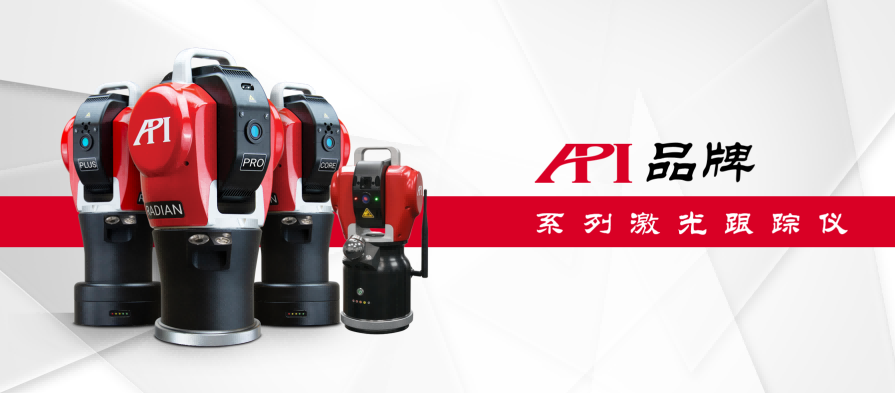
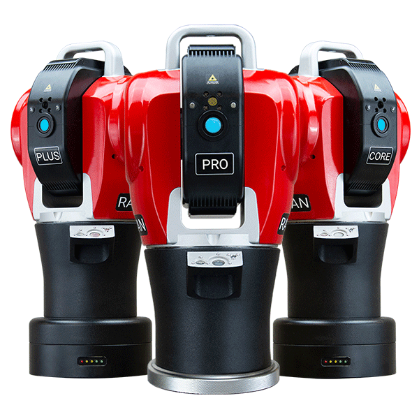
Figure 1: API brand laser tracker (from left to right: models Radian Plus / Radian Pro / Radian Core / iLT)
Advantages of using the Radian laser tracker for inspection
The API brand Radian laser tracker, with its high precision, large size, dynamic measurement, and real-time feedback characteristics, has brought revolutionary improvements to the inspection of photolithography machine bases:
1. Ultra-high precision + large measurement range: The Radian series laser trackers have micron-level spatial measurement accuracy, with a measurement radius exceeding 80 meters, fully covering the measurement range of photolithography machine bases and ensuring inspection requirements within a range of several dozen meters;
2. Unified coordinate system: By establishing a global coordinate system through the laser tracker, all inspection tasks such as surface leveling, hole position measurement, and multi-base combination adjustments can be completed under the same benchmark, eliminating benchmark conversion errors;
3. Efficient and Comprehensive: The Radian series laser tracker has a data acquisition rate of 1000Hz, allowing for rapid collection of spatial point cloud data, enabling quick and clear detection of the geometric features of the base.
4. Real-time Dynamic Guidance: During the adjustment process, the Radian laser tracker can display the deviation between the current measurement point and the theoretical position in real-time, guiding operators to make precise adjustments and transforming the serial mode of "detection-adjustment-recheck" into a parallel mode of "real-time adjustment-real-time verification."
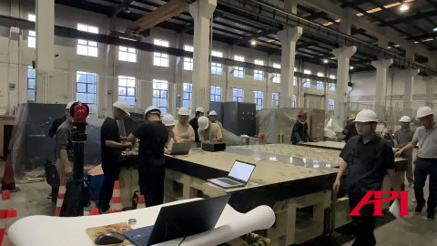
Figure 2: Measurement Site of This Case (1)
Implementation of Detection
Tracker Setup
Place the Radian laser tracker on a stable foundation or tripod at the installation site of the photolithography machine, ensuring good visibility conditions to cover all bases and measurement points, and establish the initial coordinate system.
Measurement Process
The operator holds a high-precision reflective target sphere (SMR) with a built-in prism, sequentially touching the positions to be measured or sliding it against the workpiece; the laser tracker then tracks the center point of the target sphere and measures in real-time, feeding the spatial coordinate data of the target sphere's center point back to the software for recording and subsequent analysis. For measuring the levelness of the base surface, plan the collection path on the surface and continuously collect point coordinate data; for measuring hole dimensions and positional accuracy, place the target sphere in a dedicated pin base, use the pin to fit against the hole wall to collect data, and then use data fitting and calculation analysis to determine the center coordinates, hole diameter, perimeter, and other data for each key hole position (locating pin hole, threaded hole), thus achieving positional accuracy assessment.
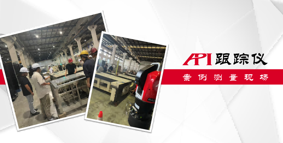
Figure 3: Measurement Site of This Case (2)
Data Analysis
All measurement data is transmitted in real-time to the supporting software systems (such as SpatialAnalyzer, PolyWorks, Verisurf, Metrolog, MeasurePro, etc.). The software performs plane fitting on the levelness data of the base platform under a unified global coordinate system, generating colored contour maps that visually display the overall flatness errors and local uneven areas; for hole size and positional accuracy, the software will automatically fit and calculate the X, Y, and Z deviations for each hole position, thus enabling the assessment of positional accuracy, and outputting the results in a list or color map format to quickly identify out-of-tolerance points.
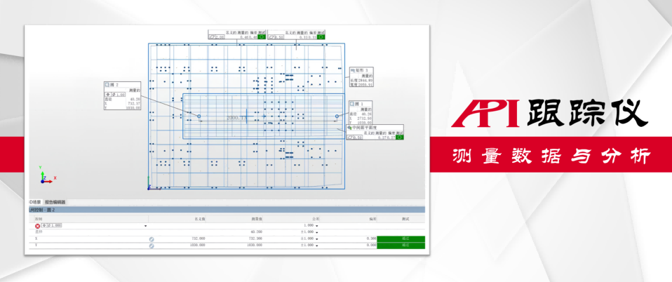
Figure 4: Measurement Data and Analysis
Issuing Analysis Report
The software automatically generates inspection reports, which include analysis charts of platform levelness, lists of positional deviations for hole locations, three-dimensional deviation cloud maps, etc. All data is traceable and can be archived, providing precise data evidence for base acceptance and subsequent photolithography machine installation.
⑤ Adjustment Function
For the positional adjustments after the combination of various bases, the Radian laser tracker incorporates the key reference points (such as reference pin holes and corner points) of multiple bases (such as bases A, B, and C) into a unified coordinate system. After setting the theoretical design coordinates, the software displays in real-time the deviation values (ΔX, ΔY, ΔZ, pitch angle, etc.) between the current actual positions of each base and the theoretical positions. Operators can make fine adjustments using the precision adjustment mechanisms (such as screws and wedge shims) beneath the bases based on the dynamic deviation data displayed on the screen, until the spatial positions and relative orientations of all bases fall within the design tolerance range. The entire process achieves precise closed-loop control of "what you see is what you get."
Summary
The application of the Radian laser tracker in the installation, debugging, and inspection of semiconductor photolithography machine bases addresses core pain points such as insufficient measurement range and accuracy, relatively low efficiency, difficulty in unifying references, and challenges in adjustment. Its capabilities for high precision, large scale, and real-time dynamic measurement not only ensure the precise control of base platform levelness, hole position accuracy, and positional adjustments of multiple bases but also provide solid technical support for the precise installation of high-end semiconductor equipment through digital and visual data management. The application of the Radian laser tracker significantly enhances installation efficiency and quality, strongly supporting the precision requirements in the front-end processes of chip manufacturing, and has become an indispensable core measurement tool in the field of precision engineering in the semiconductor industry.

Figure 5: API Company Headquarters
About API
The API brand was founded by Dr. Kam Lau in 1987 in Rockville, Maryland, USA. He is the inventor of the laser tracker and holds multiple patents in globally leading measurement technologies, making him a leader in the field of precision measurement technology. Since its establishment, API has been dedicated to the research and production of precision measuring instruments and high-performance sensors in the mechanical manufacturing sector. Its products are widely used in advanced manufacturing fields around the world and are at the forefront of high-precision standards in coordinate measurement and machine tool performance testing.
相关新闻:
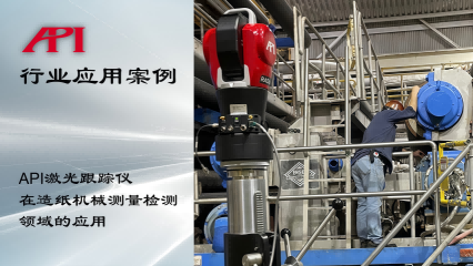
Application of API Laser Tracker in the Measurement and Detection Field of Papermaking Machinery
Detection Requirements of Papermaking Machinery In order to address issues such
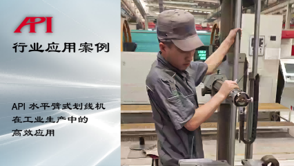
API Horizontal Arm Marking Machine Efficient Application in Industrial Production
About the Marking MachineThe marking machine is a measuring device commonly used
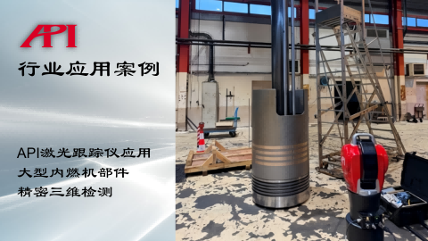
Precision 3D Inspection of Large Internal Combustion Engine Components
The Importance of 3D Inspection for Large Internal Combustion Engine ComponentsL
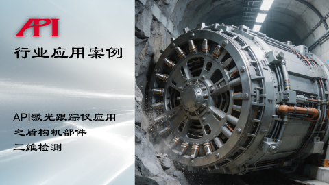
Application of API Laser Tracker in 3D Detection of Shield Machine Components
Importance of 3D Detection of Shield Machine ComponentsThe shield machine is the
Learn More:
激光跟踪仪靶球&测头
Maximize laser tracker productivity with hand held and 激光跟踪仪主动靶标.
Learn More /laser-tracker-targets
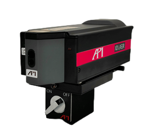
XD Laser CMM Calibration
The XD Laser is the only assessment system that can measure all 6 error parameters simultaneously in a single set-up
Learn More /xd-laser
API Reverse Engineering Service
Reverse engineering services include scan as-built parts to creation of a 3D digital point cloud and CAD Model.
Learn More /reverse-engineering/