
 +86 10 59796858
About FDM 3D Printer
FDM (Fused Deposition Modeling) printing technology refers to the construction of three-dimensional objects by layer-by-layer stacking of thermoplastic materials. This technology is widely used in the consumer-grade 3D printer field. Since this technology requires melting the filament and then stacking it layer by layer to form the shape, it inevitably produces a layer of textures on the printed parts. Poorly handled layering can affect the printing accuracy and level of detail.
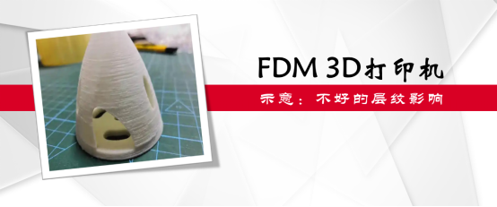
Figure 1: Illustration of Poor Layering Affect
Testing Needs of FDM 3D Printers
Based on the structural characteristics and operational characteristics of FDM 3D printers, when testing FDM 3D printers, it is often necessary to carry out tests on key indicators such as linear accuracy, straightness accuracy, verticality accuracy, and repeatability, in order to comprehensively evaluate the actual performance of the tested 3D printer, calibrate and correct any deviations, and thus ensure the performance of the 3D printer and produce printed products that meet the requirements.
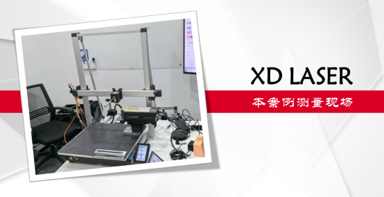
Figure 2: The 3D Printer and XD Laser Interferometer in This Case
Problems Faced by Customers
The 3D printer model to be tested by the customer is very compact, with little space to set up testing equipment. At the same time, due to the narrow internal space of the 3D printer, it requires a compact and convenient cone mirror design, and to measure as much data as possible with minimal re-mounting. Before inviting the API team to measure, the customer had tried multiple times to use multi-brand conventional laser interferometers for testing, but the results were not satisfactory.
API Solution and Advantage Analysis
After fully understanding the client's detection needs and difficulties, the API has provided a solution for the client to use the XD Laser 3D laser interferometer to inspect the 3D printer.
The XD Laser 3D laser interferometer can simultaneously detect linear and straightness accuracy with a single installation, which has certain advantages over conventional laser interferometers when implementing the above inspections. This article will explain the problems and difficulties encountered by the client in actual measurements:
Two-point Light
The XD Laser full series laser interferometers adopt a compact and highly integrated optimized optical path design, with the interferometer integrated with the host. There is no need to set up an interferometer separately; only the laser head and target need to be installed with two points of light, avoiding the complex optical path adjustment and large space requirements caused by the three-point light of conventional laser interferometers. Therefore, even for such a small 3D printer as the client's case, it can still be installed smoothly and complete the detection task smoothly.
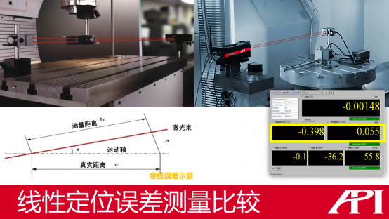
Figure 3: Linear measurement comparison between XD Laser interferometer (right) and conventional interferometer (left)
2. Effective Reduction of Cosine Error
When performing linear accuracy measurement, the three-point light characteristic of conventional laser interferometers can easily lead to cosine error (as shown in the lower left of Figure 3). During the light adjustment, the conventional laser interferometer manually performs three-point light and the adjustment can only rely on the light intensity bar in the operation software, which is very easy to cause a relatively large angle between the actual motion axis and the light path during the adjustment, thus causing a larger cosine error, making the actual measured value smaller than the true value.
However, when using the XD Laser interferometer to perform linear measurements, its two-point light characteristic, supplemented by the real-time parameter display of the digital straightness (as shown in the lower right of Figure 3), can minimize the angle between the laser light path and the motion axis in a digital form, greatly reducing the impact of cosine error.
3. Fast and Efficient Straightness Measurement
In the process of using a conventional laser interferometer for straightness measurement, in addition to the interferometer assembly, a special straightness measurement mirror assembly is also required. During adjustment, in addition to the need for the optical path to be collimated, the laser beam split to the upper/lower (or left/right) two perpendicular reflectors also needs to be kept perpendicular to the mirror surface. Moreover, even when measuring the upper/lower and left/right groups of straightness on the same axis, the mirror assembly needs to be changed again, and separate mirror assemblies for measuring the upper/lower and left/right straightness are used, and the optical path needs to be adjusted again. To measure the straightness of three axes, at least six changes of the mirror assembly and adjustment of the optical path are required. If measuring a longer axis (over 4 meters), a long-distance straightness measurement mirror assembly needs to be replaced, which is relatively more complicated.
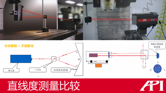
Figure 4: Comparison of straightness measurement between XD Laser laser interferometer (right) and conventional laser interferometer (left)
When using the XD Laser brand laser interferometer to measure straightness error, it is only necessary to align the light with two points, and then, by using the integrated high-performance PSD displacement sensor, it can easily and quickly detect both up and down and left and right groups of straightness data. During measurement, as shown in Figure 4, the laser emitted by the XD Laser main unit hits the target and is divided into two beams, one of which is reflected back to the main unit by the reflecting device for linear data measurement, and the other is distributed to the high-performance PSD sensor for straightness parameter measurement. As indicated by the coordinates in the lower right corner of Figure 4, when the laser hits the corresponding quadrant of the PSD sensor, the straightness parameter measurement is complete. Subsequently, the PSD sensor can convert the light signal into an electrical signal and then feedback to the operator in real-time digital display, which is simple and easy to use.
Additionally, since the conventional laser interferometer uses an interferometer group adjustment method to measure straightness data, it is not allowed to interrupt the light during the entire measurement process, so it is usually only used for the final evaluation of straightness data, and it is difficult to be applied in the real-time adjustment stage of the guide rail installation. The XD Laser laser interferometer, due to its use of high-performance PSD sensors to measure straightness parameters, ensures both measurement accuracy and excellent dynamic performance, fearlessly dealing with light interruption, and can measure, read, and display straightness parameters in real-time, making it possible to apply in the guide rail installation adjustment stage.
4. Convenient and easy-to-operate verticality measurement
Similar to straightness measurement, the conventional laser interferometer still requires complex mirror group arrangement and optical path adjustment when measuring verticality error parameters. Since verticality measurement is based on the straightness parameters of two axes, when using a conventional laser interferometer to implement verticality measurement, it is necessary to add a verticality measurement component on top of the mirror group for measuring the two-axis straightness. This requires more optical paths to be allocated to achieve data measurement and reading. Adjusting more than 10 laser optical paths is not an easy task and requires the operator to have rich adjustment experience and a good feel to adjust the optical path to a relatively optimal position and carry out measurement; to measure the mutual perpendicularity of three axes, it requires three such mirror group and optical path installation adjustments, which is relatively inefficient.
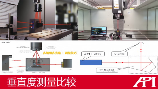
Figure 5: Comparison of verticality measurement between XD Laser laser interferometer (right) and conventional laser interferometer (left)
However, when using the XD Laser laser interferometer to measure verticality, due to the support of the high-performance PSD sensor, it is already 1:1 measured for straightness, so when measuring verticality parameters, it is only necessary to install a pentagonal prism at the corresponding position to ensure the 90-degree turn of the laser, avoiding the complex mirror group switching and optical path adjustment process when using a conventional laser interferometer, greatly improving measurement efficiency.
Considering the actual measurement scenario of the customer in this case, in addition to the above comparisons, the use of a variety of complex mirror group combinations also requires a large working space, and such a compact 3D printer cannot provide space for complex mirror group installation. This is also the reason why the customer could not successfully implement the verticality measurement of the 3D printer with many brands and models of traditional laser interferometers.
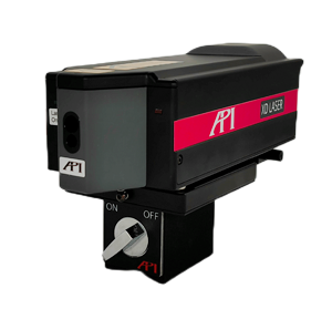
Figure 6: XD Laser laser interferometer
More Extensions
In this case, the API provides clients with the XD Laser 3D laser interferometer, which can simultaneously measure three parameters (i.e., X, Y, Z) in one installation, easily achieving the measurement and detection of straightness errors.
In addition to the 3D model, according to the different measurement application needs of a wide range of customers, the API brand also offers you 1D, 5D, and 6D models of the XD Laser interferometer. The 6D model can simultaneously measure six parameters (X, Y, Z, yaw angle, pitch angle, and roll angle) in one installation, with standard models (measurement accuracy of 0.5μm/m) and precision models (measurement accuracy of 0.2μm/m) available, fully satisfying the needs of daily production and laboratory measurements.
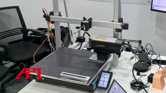
Figure 7: Measurement site in this case
Field Application
As shown in Figure 7, this is the working site where the API brand XD Laser 3D laser interferometer is used to measure and detect a small FDM 3D printer. The compact receiving mirror, combined with the bright spot for light installation, fully adapts to the customer's measurement site environment and meets the customer's measurement requirements.

Figure 8: API headquarters building
About API
The API brand was founded by Dr. Kam Lau in 1987 in Rockville, Maryland, USA, as the inventor of the laser tracker and holder of multiple global leading measurement technology patents, leading the field of precision measurement technology. Since its establishment, API has been committed to the research, development, and production of precision measurement instruments and high-performance sensors in the field of mechanical manufacturing. The products have been widely used in advanced manufacturing fields in various countries around the world and are at the forefront of high-precision standards in coordinate measurement and machine tool performance testing.
相关新闻:
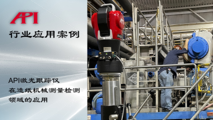
Application of API Laser Tracker in the Measurement and Detection Field of Papermaking Machinery
Detection Requirements of Papermaking Machinery In order to address issues such
API Horizontal Arm Marking Machine Efficient Application in Industrial Production
About the Marking MachineThe marking machine is a measuring device commonly used
Precision 3D Inspection of Large Internal Combustion Engine Components
The Importance of 3D Inspection for Large Internal Combustion Engine ComponentsL
Application of API Laser Tracker in 3D Detection of Shield Machine Components
Importance of 3D Detection of Shield Machine ComponentsThe shield machine is the
Learn More:
激光跟踪仪靶球&测头
Maximize laser tracker productivity with hand held and 激光跟踪仪主动靶标.
Learn More /laser-tracker-targets
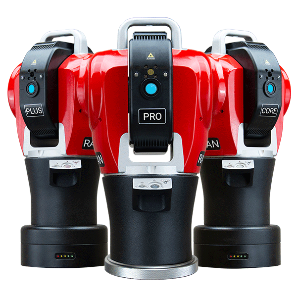
XD Laser CMM Calibration
The XD Laser is the only assessment system that can measure all 6 error parameters simultaneously in a single set-up
Learn More /xd-laser
API Reverse Engineering Service
Reverse engineering services include scan as-built parts to creation of a 3D digital point cloud and CAD Model.
Learn More /reverse-engineering/